Placement of the elements :
I was photographed while training on a normal training bike, but in recumbent position. With few pictures I could see the exact place my feet were using to spin(dark yellow). I could place my wheels in accordance.

Then I could shape the shell around the body, and design quickly an adapted structure

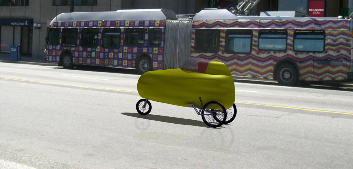
I end up by playing with photoshop to give a representation of what the velomobile could look like at the end:


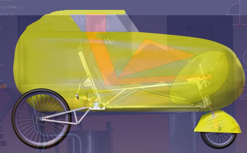
I modelised on CAD the back part of my frame with the initial penumatic jack as a tilting system. I realised few things :
The angular placement of the jack is very important : by changing this angle, we can modify the % of pression on each wheel during a tilt : more or less weight on the inside or outside wheel. This can have important influence on the stability...
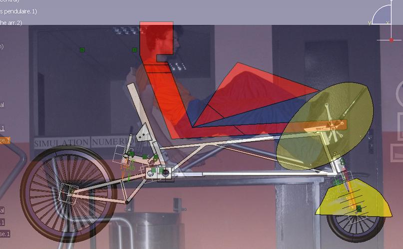
Quelques images :
Avec ma première modélisation je me suis rendu compte qu'avec une attache haute comme ceci, je devais placer les vérins devant les épaules du cycliste, sinon ca donne ceci : la deuxième image montre que le vérin ne pousse presque plus rien !

Only small openings will have to be made to prevent any interference.


=========================================================================================================
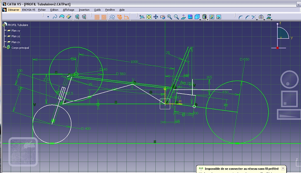
The basic designing of the frame is finished and construction can begin. It has been considerably lightened and simplified compared to the first versions.
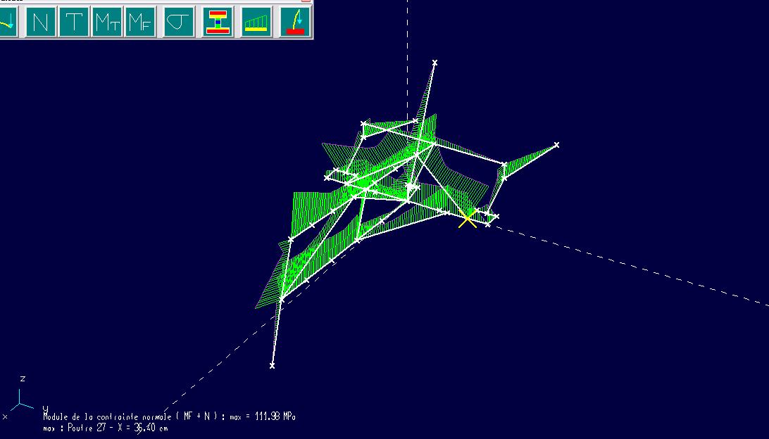
Stress simulating in a case of maximum loading and choc of 3G while driving : 111mPa max : the used allumium AGS 6060 can resist 150 mPa : all good !

As visible here, the hydrolic tilting sustem has been abandonned for a mecanic system : simple appro, and mainly : more than 10Kg saved !
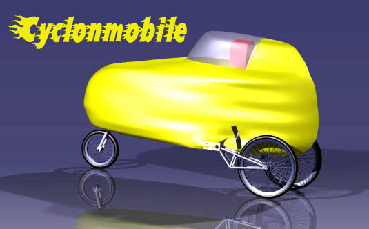
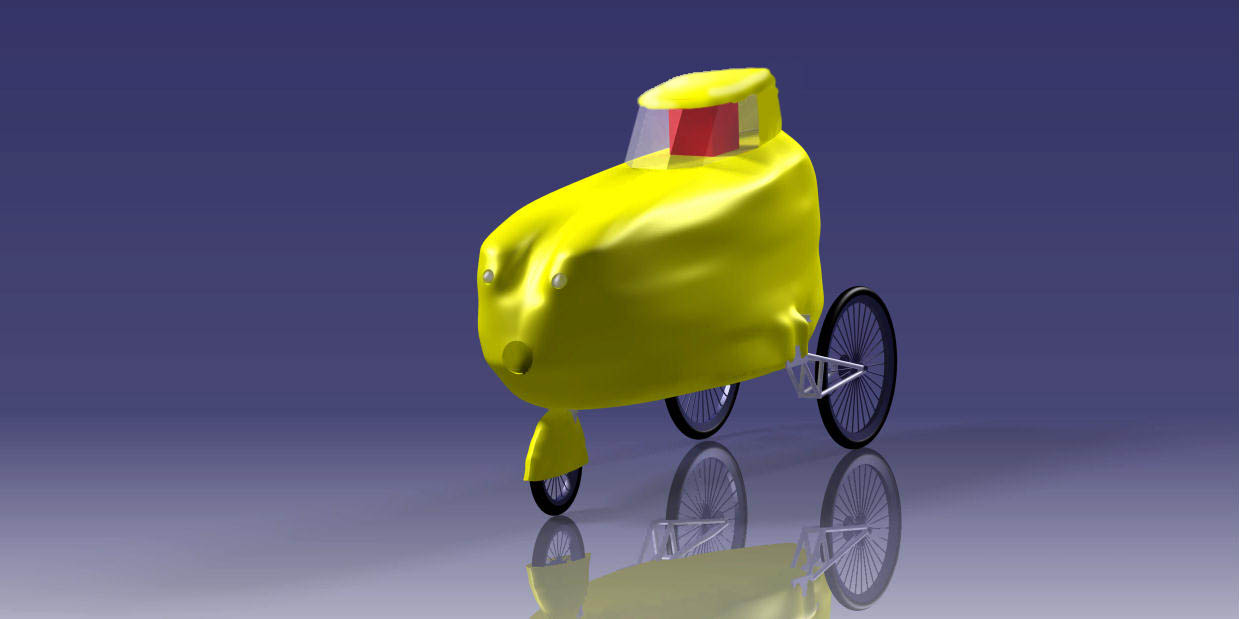
The CAD modeling has gone well, and here are the first renders!
New picture taken of the peddling movement, then replaced and redimentionned on photoshop, to create the exact interraction on Catia.
The last shell wasnt correct : there wasn't enough space for the feet. A new type of shape had to be adopted to leave enough space for feet without reducing too much the visibility.
The new shell
And a better image to have an idea of the new look.
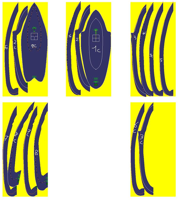
Finally, to save on (expensive) polystyrene, I used photoshop to place like in a puzzle slices of the shell, so that they re at least 10cm wide.
Like this, I bought only 5 boards of 10cm thick polystyrene instead of 8 or 9!